Clipper Module
for VCV Rack, Ⓒ Sm@rTAZZ Studio, developed by Marinko Laban
Last updated May 23rd, 2024. This manual is valid for the 2.2.0 release of the module. Older releases may not support everything stated here.Introduction
The Clipper is a module that clips or folds an audio signal, and hence adds harmonics to the signal. It can be regarded as a type of distortion. The Clipper has an independent Upper and Lower threshold, that are used to define the levels above or below which the Clipper will clip or fold the signal.
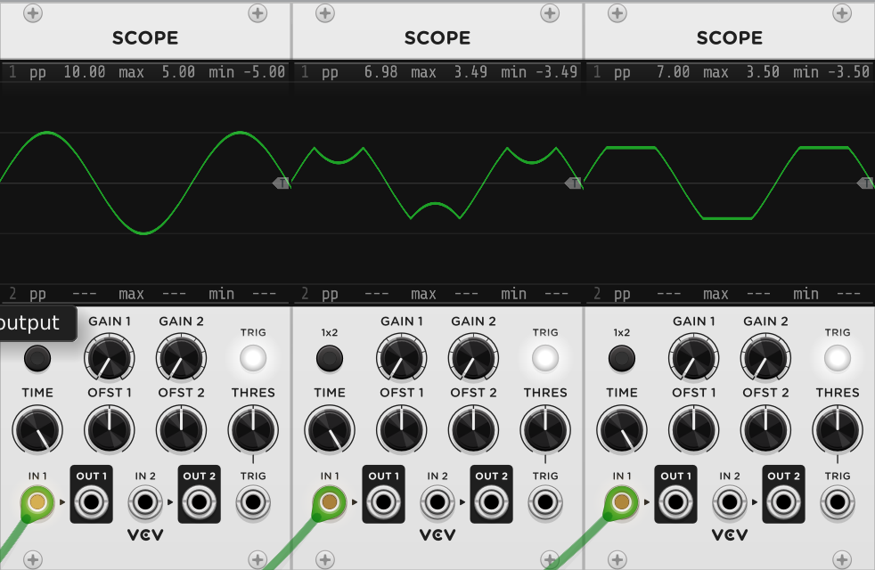
In the module menu, you can select the clip mode (Clip or Fold) and the Polarity (Bipolar or Unipolar). Clipping means the the signal is limited to the threshold. Folding means that the "overshoot" is subtracted from the threshold. The signal is kinda folded back at the threshold. Below you see a picture, showing the difference. Both the upper and lower threshold can be modulated. The modulation amount can be attenuated.

The Clipper is polyphonic. All modulation however, is applied to each polyphonic channel in the same way, so there is no option to have a different modulation or other setting per individual channel. Note that any clipping or folding reduces the level of the output signal compared to the level of the input. At this moment, the Clipper does not correct this in any way. So you may want to have an amplifier or attenuator connected to the output of the clipper. Let me know if you think it is useful to have some automatic correction done or not. When enough people ask for it, I'll bring it into a future release.
When applying any clipping or folding, bear in mind that the output signal will be enriched with harmonics. Some of these may introduce aliases. The clipper has no facilities to avoid this.
Manual
The paragraphs below describe each of the knobs, input/output jacks and menu items of the Clipper module
Panel Functions
In: An Audio input signal. This should typically be a unipolar (0..+10 V) or bipolar (-5V..+5V) signal.
Out: This is the output signal of the Clipper. It is typically sent to a VCA or mixer. It normally generates a signal with the same polarity as the input signal, but it may be trimmed by the threshold setting.
UTM-In: can be used to modulate the Upper Threshold above which clipping/folding will occur. Typically, an LFO signal can be used to modulate it, usiing the same polarity as the input signal. So, if you have an input signal that is in the -5V..+5V range, it makes sense to have the modulation signal to be in the same range.
UTM Attn: can be used to attenuate the modulation of the Upper Threshold. This means that the level of the modulation signal can be trimmed down to allow more subtle modulation. The attenuation can be set between 0.0 (no modulation) and 1.0 (maximum modulation).
LTM-In: can be used to modulate the Lower Threshold below which clipping/folding will occur. Typically, an LFO signal can be used to modulate it, usiing the same polarity as the input signal. So, if you have an input signal that is in the -5V..+5V range, it makes sense to have the modulation signal to be in the same range.
LTM Attn: can be used to attenuate the modulation of the Lower Threshold. This means that the level of the modulation signal can be trimmed down to allow more subtle modulation. The attenuation can be set between 0.0 (no modulation) and 1.0 (maximum modulation).
Upper Threshold: can be used to set the Upper Threshold of the Clipper. Note that it will be between 0..+5V for a bipolar signal and between +5V..+10V for a unipolar signal. This is to avoid situations where the Upper Threshold can become smaller than the Lower Threshold, which can cause unwanted side-effects.
Lower Threshold: can be used to set the Lower Threshold of the Clipper. Note that it will be between -5V..0V for a bipolar signal and between 0V..+5V for a unipolar signal. This is to avoid situations where the Upper Threshold can become smaller than the Lower Threshold, which can cause unwanted side-effects.
Menu Items
Clip Mode: You can select between Clip and Fold. The difference between clipping and folding is explained earlier.
Polarity: You can select between Unipolar and Bipolar. Unipolar assumes the input signal is between 0V..+10V and hence the Upper Threshold will be between +5V..+10V and the Lower Threshold will be between 0V..+5V. For Bipolar, the Upper Threshold will be between 0V..+5V and the Lower Threshold will be between -5V..0V.
You will find a tutorial below in due time (work in progress)
Source Code & Plugin
Feel free to download the source code of this module. It is part of the STS-Free bundle and the full bundle is available here on GitHub. The STS-Free bundle (slug value "SmarTAZZStudio-Free") is also available as a downloadable plugin from the VCV Rack Library, so you can download and install the module directly from VCV here.
Feedback
Feel free to feedback any comments or questions you may have. Click here to email me. You can also leave a comment in the GitHub repository with the source code.
Finally, if you want to support me in my work, feel free to buy me a coffee via the button below. It is highly appreciated and helps me to continue my work.