Ticker Module
for VCV Rack, Ⓒ Sm@rTAZZ Studio, developed by Marinko Laban
Last updated August 2nd, 2024. This manual is valid for the 2.3.0 release of the module. Older releases may not support everything stated here.Introduction
The Ticker is a clock module for VCV Rack. It supports a master clock and 4 indendent clocks for which you can set the tempo relative to the master clock. Other functions supported are gate length, phase shift and swing, which are all explained in this manual.
Manual
The Ticker is a clock, which is normally used to send gates or triggers to sequencers, envelope generators or any module that expects a gate or trigger as an input signal. The Ticker can also accept a gate or trigger as input to start or reset the module, which can be handy to reset a collection of modules or synchronize the start of multiple clocks.
Before explaining all the panel functions, it is important to understand the difference between a gate and a trigger in VCV Rack.
- A gate is a pulse that raises from 0V to 10V and stays at 10V for some time. Then it drops to 0V again. Gates are typically associated with pressing a key on a keyboard. If no key is pressed, the gate remains closed at 0V. Once you press a key, the gate opens by going up to 10V. As long as you keep the key pressed, the gate remains at 10V high or open. Once you release the key, the gate drops or closes. Gates are often used to start an ADSR or envelope generator. As long as the gate is open, the envlope progresses through it's ADS cycle. Once the gate closes, the R or release cycle starts.
- A trigger is a pulse that raises from 0V to 10V and then drops back to 0V real quickly. The duration is normally 1 ms. Triggers are typically associated with starting or stopping other modules, although you could also use a trigger as a very short gate. It is normally not that useful to control an ADSR or envelope generator, unless you require a very short and punchy ADS cycle.
Panel Functions
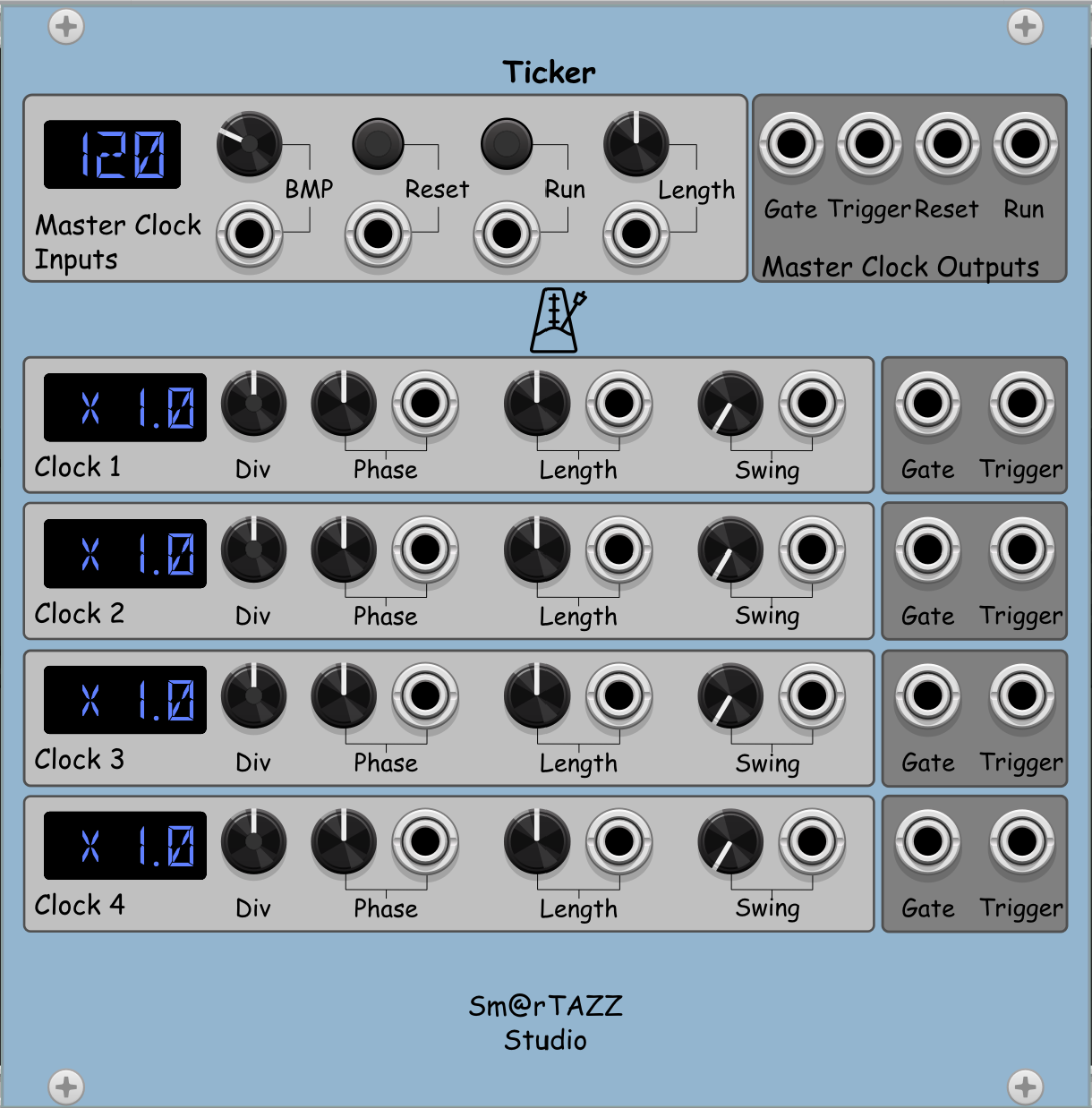
The Ticker is divided in 5 strips. The top one is for the Master Clock, the other four ar for Clocks 1 till 4. Each panel has the input settings in a light grey block on the left, and the outputs in a darker grey block on the right.
The Master Clock Panel
BPM dial: This dial is used to set the BPM (shorthand for Beats Per Minute) or tempo of the master clock. The minimum value is 10, the maximum is 400. These are fairly arbitrary boundaries, so let me know if you think they should be changed.
BPM input: This input is used to modulate or set the BPM value by an external signal, like a VCO. the input should be between 0 V (10 BPM) and 10 V (400 BPM). The response is linear, so a 5 V signal would equate to 205 BPM. The display will show the BPM value, either as set by the dial or by the input signal.
Reset button: This button is used to reset the clock, meaning that it stops running, sets all clock phases back to 0.0 and sends a reset pulse to the Reset output jack in the Master Clock Outputs section. This is done so you can forward a reset pulse to other modules as well. Note that a Reset keeps all the other parameters unchanged. In that sense, it is not the same as an Initialize via the menu. This will set all values back to the defaults, so any parameter changes you may have done, will be gone.
Reset input: This input is used to receive a Reset signal from some external source, like another clock. When a signal higher than 2.0 V is sent to this input, it will consider it as a Reset signal. It will execute the reset as if the reset button was pushed. It will also wait until the input signal drops below 0.1 V before it accepts another reset.
Run button: This button is used to start or stop the clock. Once started, it will send a gate and trigger to the respective output jacks in the Master Clock Outputs section. It will also light up a yellow light in the centre of the BPM dial, for the duration of the gate.
Run input: This input is used to receive a Run signal from some external source, like another clock. When a signal higher than 2.0 V is sent to this input, it will consider it as a Run signal. It will execute the start (or stop) as if the Run button was pushed. It will also wait until the input signal drops below 0.1 V before it accepts another Run. Note that unlike the Reset, the Run is functioning as an alternating start/stop button or signal. Pressing the button once will start the clock. Pressing it again will stop the clock.
Length dial: This dial is used to set the length or duration of the gate pulse that is sent to the Gate output in the Master Clock Outputs section. The gate length is defined as a % of a full cycle. The default is 50%, meaning that the gate will have a duration of half a cycle. So for example, if you have set the BPM to 120, it means a cycle takes 60/120 = 0.5 seconds, and therefore the gate will last 0.25 seconds. If you set the gate to e.g. 10%, it would last 0.05 seconds. The gate length can be set between 10% and 90%. These values are chosen to allow for enough headroom to implement swing without the risk of overlapping gates.
Length input: This input is used to modulate or set the lenght value by an external signal. It assumed a unipolar signal between in the 0..10V range and maps this into a value between 5% and 95%. See also the Length dial explanation above.
Gate output: The master clock gate signal is sent to this output.
Trigger output: The master clock trigger signal is sent to this output, at the same moment the gate signal is sent.
Reset output: When the module receives a Reset signal, or the Reset button is pushed, a trigger is sent to this output. You can use it to pass a reset signal on to other modules, so they all receive a reset in sync.
Run output: When the module receives a Run signal, or the Run button is pushed, a trigger is sent to this output. You can use it to pass a Start or Stop signal on to other modules, so they all receive a reset in sync.
The Clock 1 Panel
This section applies to the Clock 1 till 4 panels.
Div dial: This is used to set the speed or tempo of the clock, relative to the master clock. The dial takes 73 positions, which translate into dividing or multiplying the master clock BPM value by a specific factor. The display will show if a division is taking place ("/") or a multiplication ("x") of the master clock and with which factor. Most useful factors are supported, all between / 96 or x 96. Let me know if you miss a specific value, so I can add it.
Phase dial: This allows you to shift the gate (and trigger) by half a cycle left or right. This can be used to add an offset of the gate and trigger, so it always arrives earlier or later. Note that this is an epxerimental feature and is not fully stable yet.
Phase input: This allows you to shift the gate (and trigger) by a cycle based on a unipolar input between 0V and 10V. This can be used to add an offset of the gate and trigger, so it always arrives earlier or later. Note that this is an epxerimental feature and is not fully stable yet.
Length dial: This dial is used to set the length or duration of the gate pulse that is sent to the Gate output in the Master Clock Outputs section. The gate length is defined as a % of a full cycle. The default is 50%, meaning that the gate will have a duration of half a cycle. So for example, if you have set the BPM to 120, it means a cycle takes 60/120 = 0.5 seconds, and therefore the gate will last 0.25 seconds. If you set the gate to e.g. 10%, it would last 0.05 seconds. The gate length can be set between 5% and 95%. These values are chosen to allow for enough headroom to implement swing without the risk of overlapping gates.
Length input: This input is used to modulate or set the lenght value by an external signal. It assumed a unipolar signal between in the 0..10V range and maps this into a value between 5% and 95%. See also the Length dial explanation above.
Swing dial: This dial controls a random amount of swing to each gate or pulse. It has a maximum value of 10% of the total cycle, and behaves as a phase shift. After every gate, a new random value is determined to displace the next gate and trigger. The displacement can be positive (later) or negative (earlier). With higher tempo's, the % of swing becomes smaller as an absolute time shift, and is therefore less noticable. With lower tempo's, the shift can be quite noticable, so you may want to adjust it a bit.
Swing input: This input can be used to modulate or set the swing amount by an external signal. It assumes a unipolar signal between 0V and 10V, which is mapped to -5%..5%.
Menu Items
The Ticker has no specific menu options, only the default VCV Rack menu.
You will find a tutorial below in due time (work in progress)
Source Code & Plugin
Feel free to download the source code of this module. It is part of the STS-Free bundle and the full bundle is available here on GitHub. The STS-Free bundle (slug value "SmarTAZZStudio-Free") is also available as a downloadable plugin from the VCV Rack Library, so you can download and install the module directly from VCV here.
Feedback
Feel free to feedback any comments or questions you may have. Click here to email me. You can also leave a comment in the GitHub repository with the source code.
Finally, if you want to support me in my work, feel free to buy me a coffee via the button below. It is highly appreciated and helps me to continue my work.